
xSignal allows you to examine signals in a more three-dimensional way than a spectrogram. This new capability makes it easier to identify suspect signals and locate rogue pulse trains.
Select source components, nets, and destination components for which you want to create xSignals. Click the Analyze button and xSignals are identified between these selected components, including through series components if needed.
1. Real-Time Display
Many analog ignition analyzers can provide a real-time display of an analog signal. This is accomplished by sampling the time varying voltage of the ignition signal to create digital values. These values are then accessed to raster a display beam across the screen in real time.
The left panel region lists any xSignal classes that have been defined (All xSignals>). The right-click context menu offers the ability to Add Class, Change xSignal Color and remove (Delete) a class.
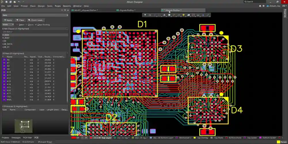
The middle region displays xSignals in the PCB design space as node pads joined by a thin line that represents the xSignal path. The selected xSignal is highlighted in yellow and is moved proportionally to the stored data in the time overview bar.
2. Sin X/X Interpolation
A continuous band limited signal is only defined at a few points in time (samples). Therefore, some form of interpolation is needed to fill the gaps between these samples.
Sinc interpolation is the only one that is algebraically exact for a bandwidth-limited signal. However, if the sampling frequency is too close to the Nyquist limit then sinc interpolation can result in pre- and overshoot artifacts.
For this reason, most DSOs use bezier or polyline type interpolation for visual representation of the signal. This is less accurate but prettier than linear and preserves the original data points.
3. Trigger Controls
The trigger control helps stabilize repetitive waveforms and capture single-shot waveforms. It also adjusts for jitter between the hardware trigger and the data acquisition system.
To create an xSignal, select the start pad and the end pad from the PCB panel in the xSignals mode. The xSignal will be named by the net name (separated by a hyphen) and the routing topology defined for that net – currently this is set to Shortest.
The xSignal can also be associated with an xSignal class, which you can specify by clicking in the xSignals Classes region of the panel. You can choose a class from existing ones or create a new one and add members to it.
4. XYZ Mode
The XYZ Mode feature enables you to work with high-speed signals by viewing them as a single path, rather than as separate pins in connected nets. This helps ensure compliance with key design rules, such as the Length and Matched Length design rules.
The middle region displays any xSignal classes that have been defined, or all available classes (All xSignals>). Use the management buttons to select and edit a class.
In model mode, the numeric keypad arrow keys move the current image point laterally, and the PageUp and PageDown keys move the current slice through the planes in the view box.
5. XYZ Record Display
The XYZ mode lets you record and display a sequence of points from a 3D file. This can be useful when trying to locate a specific point in the data.
XYZ files may contain multiple frames of a simulation trajectories, stored back-to-back in the same file. Each frame contains a new header line followed by a list of atoms. OVITO can load XYZ files with an arbitrary number of text columns containing auxiliary particle properties.
The XYZ File Options dialog lets you specify the mapping of each auxiliary data column to an OVITO particle property. The default mapping is to map the atoms list to the Particle Identifier property.
6. Horizontal Position Control
The horizontal position control feature lets you set how far the waveform moves left or right on your screen. This control works in tandem with the seconds-per-divide setting, which sets how much of your signal is represented by a single horizontal division.
Changing the sec/div setting lets you zoom in on your signals and see them at shorter or longer time intervals. This is useful for identifying a specific component’s behavior at high speeds.
In the PCB panel, the third region shows all xSignal classes collected in your design (All xSignals>). Select an xSignal class to display its node pads as a thin line in the PCB design space.
7. Sample Rate
When using a DSO to analyze signals in the time domain the proper lowpass frequency and sampling rate are critical. If the sample rate is too low, the digitized signal will not accurately represent the original analog signal. If the sample rate is too high, it will cause aliasing which will make certain frequencies indistinguishable.
To avoid these errors, xSignal provides the ability to correctly treat a high-speed signal path as a single xSignal that is scoped by relevant design rules such as Length and Matched Length. This is achieved by selecting a pad in the PCB editor and running the xSignals >> Create xSignal from connected nets command or by right-clicking on the component and selecting this option.